What is used to purify water at stations. Types and purposes of treatment facilities
The third belt covers the area surrounding the source, which affects the formation of water quality in it. The boundaries of the territory of the third belt are determined based on the possibility of contamination of the source with chemicals.
1.8. Water treatment facilities
Water quality indicators. The main source of prices
The trawled domestic and drinking water supply in most regions of the Russian Federation is the surface water of rivers, reservoirs and lakes. The amount of pollution entering surface water sources is varied and depends on the profile and volume of industrial and agricultural enterprises located in the catchment area.
The quality of groundwater is quite diverse and depends on the conditions of groundwater recharge, the depth of the aquifer, the composition of water-bearing rocks, etc.
Water quality indicators are divided into physical, chemical, biological and bacterial. To determine the quality of natural waters, appropriate analyzes are carried out in the most characteristic periods of the year for a given source.
to physical indicators include temperature, transparency (or turbidity), color, smell, taste.
The water temperature of underground sources is characterized by constancy and is in the range of 8 ... be within t = 7…10 o C, at t< 7 о C вода плохо очищается, при t >10 o C, bacteria multiply in it.
Transparency (or turbidity) is characterized by the presence of suspended solids (particles of sand, clay, silt) in the water. The concentration of suspended solids is determined by weight.
The maximum permissible content of suspended solids in drinking water should not exceed 1.5 mg/l.
The color of the water is due to the presence of humic substances in the water. The color of water is measured in degrees of the platinum-cobalt scale. For drinking water, a color of no more than 20 ° is allowed.
Tastes and smells of natural waters can be of natural and artificial origin. There are three main tastes of natural water: salty, bitter, sour. Shades of taste sensations, composed of the main ones, are called flavors.
TO odors of natural origin include earthy, fishy, putrid, marsh, etc. Odors of artificial origin include chlorine, phenolic, oil products, etc.
The intensity and nature of smells and tastes of natural water is determined organoleptically, with the help of human senses on a five-point scale. Drinking water may have an odor and taste with an intensity of no more than 2 points.
TO chemical indicators include: ionic composition, hardness, alkalinity, oxidizability, active concentration of hydrogen ions (pH), dry residue (total salt content), as well as the content of dissolved oxygen, sulfates and chlorides, nitrogen-containing compounds, fluorine and iron in water.
Ionic composition, (mg-eq/l) - natural waters contain various dissolved salts, represented by cations Ca + 2 , Mg + 2 , Na + , K + and anions HCO3 - , SO4 -2 , Cl- . Analysis of the ionic composition allows you to identify other chemical indicators.
Water hardness, (mg-eq / l) - due to the presence of calcium and magnesium salts in it. Distinguish between carbonate and non-carbonate hard
bone, their sum determines the total hardness of water, Zho \u003d Zhk + Zhnk. Carbonate hardness is due to the content of carbonate in water.
sodium and bicarbonate salts of calcium and magnesium. Non-carbonate hardness is due to calcium and magnesium salts of sulfuric, hydrochloric, silicic and nitric acids.
Water for household and drinking purposes should have a total hardness of not more than 7 mg-eq / l.
Alkalinity of water, (mg-eq/l) - due to the presence of bicarbonates and salts of weak organic acids in natural water.
The total alkalinity of water is determined by the total content of anions in it: HCO3 -, CO3 -2, OH-.
For drinking water, alkalinity is not limited. The oxidizability of water (mg / l) - due to the presence of or-
organic substances. Oxidability is determined by the amount of oxygen required for the oxidation of organic substances in 1 liter of water. A sharp increase in the oxidizability of water (more than 40 mg/l) indicates its contamination with domestic wastewater.
The active concentration of hydrogen ions in water is an indicator characterizing the degree of its acidity or alkalinity. Quantitatively, it is characterized by the concentration of hydrogen ions. In practice, the active reaction of water is expressed by the pH indicator, which is the negative decimal logarithm of the concentration of hydrogen ions: pH = - lg [Н + ]. The pH value of water is 1…14.
Natural waters are classified by pH value: into acidic pH< 7; нейтральные рН = 7; щелочные рН > 7.
For drinking purposes, water is considered suitable at pH = 6.5 ... 8.5. The salinity of water is estimated by dry residue (mg / l): pre-
sleepy100…1000; salted 3000…10000; heavily salted 10000 ... 50000.
In the water of domestic drinking water supply sources, the dry residue should not exceed 1000 mg/l. With a greater mineralization of water in the human body, salt deposition is observed.
Dissolved oxygen enters water when it comes into contact with air. The oxygen content in water depends on temperature and pressure.
IN dissolved oxygen is not found in artesian waters,
A its concentration in surface waters is significant.
IN In surface waters, the content of dissolved oxygen decreases when there are processes of fermentation or decay of organic residues in the water. A sharp decrease in the content of dissolved oxygen in water indicates its organic pollution. In natural water, the content of dissolved oxygen should not be
less than 4 mg O2 / l.
Sulfates and chlorides - due to their high solubility, they are found in all natural waters, usually in the form of sodium, calcium
calcium and magnesium salts: CaSO4, MgSO4, CaCI2, MgCl2, NaCl.
IN drinking water content of sulfates is recommended not higher than 500 mg/l, chlorides - up to 350 mg/l.
Nitrogen-containing compounds - are present in water in the form of ammonium ions NH4 +, nitrites NO2 - and nitrates NO3 -. Nitrogen-containing pollution indicates the contamination of natural waters with domestic wastewater and effluents from chemical plants. The absence of ammonia in the water and at the same time the presence of nitrites and especially nitrates indicate that the pollution of the reservoir occurred a long time ago, and the water
self-purifying. At high concentrations of dissolved oxygen in water, all nitrogen compounds are oxidized to NO3 - ions.
The presence of nitrates NO3 - in natural water up to 45 mg / l, ammonium nitrogen NH4 + is considered acceptable.
Fluorine - in natural water is contained in an amount of up to 18 ml / l and more. However, the vast majority of surface sources are characterized by the content of fluorine in the water - an ion of up to 0.5 mg / l.
Fluorine is a biologically active trace element, the amount of which in drinking water in order to avoid caries and fluorosis should be in the range of 0.7 ... 1.5 mg / l.
Iron - quite often found in the water of underground sources, mainly in the form of dissolved ferrous bicarbonate Fe (HCO3) 2 . In surface waters, iron is less common and usually in the form of complex complex compounds, colloids, or finely dispersed suspensions. The presence of iron in natural water makes it unsuitable for drinking and industrial purposes.
hydrogen sulfide H2S.
Bacteriological indicators - It is customary to consider the total number of bacteria and the number of E. coli contained in 1 ml of water.
Of particular importance for the sanitary assessment of water is the definition of bacteria of the Escherichia coli group. The presence of E. coli indicates water pollution by fecal effluents and the possibility of pathogenic bacteria, in particular typhoid bacteria, entering the water.
Bacteriological contaminants are pathogenic (pathogenic) bacteria and viruses that live and develop in water, which can cause typhoid fever,
paratyphoid, dysentery, brucellosis, infectious hepatitis, anthrax, cholera, poliomyelitis.
There are two indicators of bacteriological water pollution: coli-titer and coli-index.
Coli-titer - the amount of water in ml per one Escherichia coli.
Coli index - the number of Escherichia coli in 1 liter of water. For drinking water, if the titer should be at least 300 ml, if the index is not more than 3 Escherichia coli. Total number of bacteria
in 1 ml of water, no more than 100 is allowed.
Schematic diagram of water treatment facilities
ny. Treatment facilities are one of the constituent elements of water supply systems and are closely related to its other elements. The location of the treatment plant is assigned when choosing a water supply scheme for the facility. Often, treatment facilities are located near the source of water supply and at a slight distance from the pumping station of the first lift.
Traditional water treatment technologies provide for water treatment according to classical two-stage or one-stage schemes based on the use of microfiltration (in cases where algae are present in the water in an amount of more than 1000 cells / ml), coagulation followed by sedimentation or clarification in a layer of suspended sediment, rapid filtration or contact clarification and disinfection. The most widespread in the practice of water treatment are schemes with gravity flow of water.
A two-stage scheme for preparing water for domestic and drinking purposes is shown in fig. 1.8.1.
The water supplied by the pumping station of the first lift enters the mixer, where the coagulant solution is introduced and where it is mixed with water. From the mixer, water enters the flocculation chamber and sequentially passes through a horizontal sump and a quick filter. The clarified water enters the clean water tank. Chlorine from the chlorinator is introduced into the pipe supplying water to the tank. The contact with chlorine necessary for disinfection is provided in a clean water tank. In some cases, chlorine is added to the water twice: before the mixer (primary chlorination) and after the filters (secondary chlorination). In case of insufficient alkalinity of the source water into the mixer simultaneously with the coagulant
lime solution is supplied. To intensify the coagulation processes, a flocculant is introduced in front of the flocculation chamber or filters.
If the source water has a taste and smell, activated carbon is introduced through a dispenser before settling tanks or filters.
Reagents are prepared in special apparatus located in the premises of the reagent facilities.
From the pumps of the first |
To pumps |
||||||||||||||
Rice. 1.8.1. Scheme of treatment facilities for water purification for household and drinking purposes: 1 - mixer; 2 - reagent facilities; 3 - flocculation chamber; 4 - sump; 5 - filters; 6 − clean water tank; 7 - chlorination
With a single-stage water purification scheme, its clarification is carried out on filters or in contact clarifiers. When treating low-turbid colored waters, a single-stage scheme is used.
Let us consider in more detail the essence of the main processes of water purification. Coagulation of impurities is the process of enlargement of the smallest colloidal particles occurring as a result of their mutual adhesion under the influence of molecular attraction.
Colloidal particles contained in water have negative charges and are in mutual repulsion, so they do not settle. The added coagulant forms positively charged ions, which contributes to the mutual attraction of oppositely charged colloids and leads to the formation of coarse particles (flakes) in the flocculation chambers.
Aluminum sulfate, ferrous sulfate, aluminum polyoxychloride are used as coagulants.
The coagulation process is described by the following chemical reactions
Al2 (SO4 )3 → 2Al3+ + 3SO4 2– .
After the introduction of a coagulant into the water, aluminum cations interact with it
Al3+ + 3H2 O =Al(OH)3 ↓+ 3H+ .

Hydrogen cations are bound by bicarbonates present in water:
H+ + HCO3 – → CO2 + H2O.
soda is added to the water:
2H+ + CO3 –2 → H2O + CO2 .
The clarification process can be intensified with the help of high-molecular flocculants (praestol, VPK - 402), which are introduced into the water after the mixer.
Thorough mixing of treated water with reagents is carried out in mixers of various designs. The mixing of reagents with water should be fast and carried out within 1–2 min. The following types of mixers are used: perforated (Fig. 1.8.2), cloisonne (Fig. 1.8.3) and vertical (vortex) mixers.
+β h1 |
|||||||||||||||||
2bl |
|||||||||||||||||
Rice. 1.8.2. perforated mixer |
Rice. 1.8.3. Partition mixer |
||||||||||||||||
The perforated type mixer is used in water treatment plants with a capacity of up to 1000 m3 / h. It is made in the form of a reinforced concrete tray with vertical partitions installed perpendicular to the movement of water and equipped with holes arranged in several rows.
The partition wall mixer is used at water treatment plants with a capacity of not more than 500–600 m3 / h. The mixer consists of a tray with three transverse vertical partitions. In the first and third partitions, water passages are arranged, located in the central part of the partitions. In the middle partition there are two side passages for water adjacent to

tray walls. Due to this design of the mixer, turbulence of the moving water flow occurs, which ensures complete mixing of the reagent with water.
At stations where water is treated with lime milk, the use of perforated and partition mixers is not recommended, since the speed of water movement in these mixers does not ensure that lime particles are kept in suspension, which leads to
dit to their deposition in front of partitions. |
||||||||||
At water treatment plants, most |
||||||||||
found more use vertically |
||||||||||
mixers (Fig. 1.8.4). Mixer |
||||||||||
this type can be square or |
||||||||||
round section in plan, with pyramids - |
||||||||||
far or conical bottom. |
||||||||||
In partition chambers, flakes |
||||||||||
formations arrange a series of partitions |
||||||||||
dock that make the water change |
Reagents |
|||||||||
direction of movement or |
||||||||||
vertical or horizontal |
||||||||||
plane, which provides the necessary |
||||||||||
dimmable mixing of water. |
Rice. 1.8.4. Vertical |
|||||||||
For mixing water and providing |
||||||||||
roar) mixer: 1 - feed |
||||||||||
more complete agglomeration |
source water; 2 - water outlet |
|||||||||
small flakes of coagulant into large |
from mixer |
|||||||||
serve as flocculation chambers. Their |
||||||||||
installation is necessary in front of horizontal and vertical sedimentation tanks. With horizontal settling tanks, the following types of flocculation chambers should be arranged: partitioned, vortex, built-in with a layer of suspended sediment and paddle; with vertical sedimentation tanks - whirlpool.
Removal of suspended solids from water (clarification) is carried out by settling it in settling tanks. In the direction of water movement, sedimentation tanks are horizontal, radial and vertical.
The horizontal settling tank (Fig. 1.8.5) is a reinforced concrete tank rectangular in plan. In its lower part there is a volume for the accumulation of sediment, which is removed through the channel. For more efficient removal of sediment, the bottom of the sump is made with a slope. The treated water enters through the distribution
flume (or flooded weir). After passing through the sump, the water is collected by a tray or a perforated (perforated) pipe. Recently, settling tanks with a dispersed collection of clarified water have been used, arranging special gutters or perforated pipes in their upper part, which makes it possible to increase the performance of settling tanks. Horizontal settling tanks are used at treatment plants with a capacity of more than 30,000 m3 / day.
A variation of horizontal settling tanks are radial settling tanks with a mechanism for raking sediment into a pit located in the center of the structure. The sludge is pumped out of the pit. The design of radial sedimentation tanks is more complicated than horizontal ones. They are used to clarify waters with a high content of suspended solids (more than 2 g/l) and in circulating water supply systems.
Vertical settling tanks (Fig. 1.8.6) are round or square in plan and have a conical or pyramidal bottom for sediment accumulation. These settling tanks are used under the condition of preliminary coagulation of water. The flocculation chamber, mostly whirlpool, is located in the center of the structure. Clarification of water occurs with its upward movement. Clarified water is collected in circular and radial trays. Sludge from vertical settling tanks is discharged under hydrostatic water pressure without shutting down the facility from operation. Vertical settling tanks are mainly used at a flow rate of 3000 m3 / day.
Clarifiers with suspended sludge bed are designed for pre-clarification of water before filtration and only in case of pre-coagulation.
Sludge suspended bed clarifiers can be of various types. One of the most common is the in-line clarifier (Fig. 1.8.7), which is a rectangular tank divided into three sections. The two extreme sections are clarifier working chambers, and the middle section serves as a sediment thickener. The clarified water is supplied at the bottom of the clarifier through perforated pipes and is evenly distributed over the area of the clarifier. Then it passes through the suspended sediment layer, is clarified and is discharged to the filters through a perforated tray or pipe located at some distance above the surface of the suspended layer.
For deep clarification of water, filters are used that are able to capture almost all suspensions from it. There are so

the same filters for partial water purification. Depending on the nature and type of filter material, the following types of filters are distinguished: granular (filter layer - quartz sand, anthracite, expanded clay, burnt rocks, granodiarite, expanded polystyrene, etc.); mesh (filter layer - mesh with a mesh size of 20-60 microns); fabric (filter layer - cotton, linen, cloth, glass or nylon fabrics); alluvial (filter layer - wood flour, diatomite, asbestos chips and other materials, laundered in the form of a thin layer on a frame made of porous ceramics, metal mesh or synthetic fabric).
Rice. 1.8.5. Horizontal sump: 1 - source water supply; 2 - removal of purified water; 3 - sediment removal; 4 - distribution pockets; 5 - distribution grids; 6 – sediment accumulation zone;
7 - settling zone
Rice. 1.8.6. Vertical settler: 1 – flocculation chamber; 2 - Rochelle wheel with nozzles; 3 - absorber; 4 - supply of initial water (from the mixer); 5 - prefabricated chute of the vertical sump; 6 - a pipe for removing sediment from a vertical sump; 7 - branch
water from the sump
Granular filters are used to purify domestic and industrial water from fine suspensions and colloids; mesh - to retain coarse suspended and floating particles; fabric - for the treatment of low-turbidity waters at stations of small productivity.
Grain filters are used to purify water in municipal water supply. The most important characteristic of the filters operation is the filtration speed, depending on which the filters are divided into slow (0.1–0.2), fast (5.5–12) and superfast filters.
![]()
Rice. 1.8.7. Corridor clarifier with suspended sludge with a vertical sludge thickener: 1 - clarifier corridors; 2 – sediment thickener; 3 - supply of initial water; 4 - prefabricated pockets for the removal of clarified water; 5 – sludge removal from the sludge thickener; 6 - removal of clarified water from the sediment thickener; 7 - sedimentation
windows with canopies
The most widespread are fast filters, on which pre-coagulated water is clarified (Fig. 1.8.8).
The water entering the rapid filters after the sump or clarifier should not contain suspended solids more than 12–25 mg/l, and after filtering the water turbidity should not exceed 1.5 mg/l
Contact clarifiers are similar in design to quick filters and are a variation of them. Clarification of water, based on the phenomenon of contact coagulation, occurs when it moves from bottom to top. The coagulant is introduced into the treated water immediately before it is filtered through the sand bed. In the short time before the start of filtration, only the smallest flakes of suspension are formed. The further process of coagulation takes place on the grains of the load, to which the smallest flakes previously formed adhere. This process, called contact coagulation, is faster than conventional bulk coagulation and requires less coagulant. Contact clarifiers are washed with
Water disinfection. In modern treatment facilities, water disinfection is carried out in all cases when the source of water supply is unreliable from a sanitary point of view. Disinfection can be carried out by chlorination, ozonation and bactericidal irradiation.
Water chlorination. The method of chlorination is the most common method of water disinfection. Usually, liquid or gaseous chlorine is used for chlorination. Chlorine has a high disinfecting ability, is relatively stable and remains active for a long time. It is easy to dose and control. Chlorine acts on organic substances, oxidizing them, and on bacteria, which die as a result of oxidation of substances that make up the protoplasm of cells. The disadvantage of water disinfection with chlorine is the formation of toxic volatile organohalogen compounds.
One of the promising methods of water chlorination is the use of sodium hypochlorite(NaClO), obtained by electrolysis of 2-4% sodium chloride solution.
Chlorine dioxide (ClO2 ) helps to reduce the possibility of formation of by-product organochlorine compounds. The bactericidal activity of chlorine dioxide is higher than that of chlorine. Chlorine dioxide is especially effective in disinfecting water with a high content of organic substances and ammonium salts.
The residual concentration of chlorine in drinking water should not exceed 0.3–0.5 mg/l
The interaction of chlorine with water is carried out in contact tanks. The duration of contact of chlorine with water before it reaches consumers should be at least 0.5 hours.
Germicidal irradiation. The bactericidal property of ultraviolet rays (UV) is due to the effect on cell metabolism and especially on the enzyme systems of a bacterial cell, in addition, under the action of UV radiation, photochemical reactions occur in the structure of DNA and RNA molecules, leading to their irreversible damage. UV rays destroy not only vegetative, but also spore bacteria, while chlorine acts only on vegetative ones. The advantages of UV radiation include the absence of any effect on the chemical composition of water.
To disinfect water in this way, it is passed through an installation consisting of a number of special chambers, inside which mercury-quartz lamps are placed, enclosed in quartz casings. Mercury-quartz lamps emit ultraviolet radiation. The productivity of such an installation, depending on the number of chambers, is 30 ... 150 m3 / h.
Operating costs for water disinfection by irradiation and chlorination are approximately the same.
However, it should be noted that with bactericidal irradiation of water, it is difficult to control the disinfection effect, while with chlorination this control is carried out quite simply by the presence of residual chlorine in the water. In addition, this method cannot be used to disinfect water with increased turbidity and color.
Water ozonation. Ozone is used for the purpose of deep water purification and oxidation of specific organic pollution of anthropogenic origin (phenols, petroleum products, synthetic surfactants, amines, etc.). Ozone improves the course of coagulation processes, reduces the dose of chlorine and coagulant, reduces the concentration
ration of LGS, to improve the quality of drinking water in terms of microbiological and organic indicators.
Ozone is most appropriate to use in conjunction with sorption purification on active carbons. Without ozone, in many cases it is impossible to obtain water that complies with SanPiN. As the main products of the reaction of ozone with organic substances, such compounds as formaldehyde and acetaldehyde are called, the content of which is normalized in drinking water at the level of 0.05 and 0.25 mg/l, respectively.
Ozonation is based on the property of ozone to decompose in water with the formation of atomic oxygen, which destroys the enzyme systems of microbial cells and oxidizes some compounds. The amount of ozone required for the disinfection of drinking water depends on the degree of water pollution and is not more than 0.3–0.5 mg/l. Ozone is toxic. The maximum permissible content of this gas in the air of industrial premises is 0.1 g/m3.
Water disinfection by ozonation according to sanitary and technical standards is the best, but relatively expensive. A water ozonation plant is a complex and expensive set of mechanisms and equipment. A significant disadvantage of the ozonator plant is the significant consumption of electricity to obtain purified ozone from the air and supply it to the treated water.
Ozone, being the strongest oxidizing agent, can be used not only to disinfect water, but also to decolorize it, as well as to eliminate tastes and odors.
The dose of ozone required for the disinfection of clean water does not exceed 1 mg/l, for the oxidation of organic substances during water discoloration - 4 mg/l.
The duration of contact of disinfected water with ozone is approximately 5 minutes.
Due to the fact that the volumes of water consumption are constantly growing, and groundwater sources are limited, the shortage of water is replenished at the expense of surface water bodies.
The quality of drinking water must meet the high requirements of the standard. And the quality of water used for industrial purposes depends on the normal and stable operation of devices and equipment. Therefore, this water must be well purified and meet the standards.
But in most cases, the quality of water is low, and the problem of water purification is of great relevance today.
It is possible to improve the quality of wastewater treatment, which is then planned to be used for drinking and for household purposes, by using special methods for their treatment. For this, complexes of treatment facilities are being built, which are then combined into water treatment plants.
 But attention should be paid to the problem of purifying not only the water that will then be eaten. Any wastewater, after passing through certain stages of purification, is discharged into water bodies or onto land. And if they contain harmful impurities, and their concentration is higher than the permissible values, then a serious blow is dealt to the state of the environment. Therefore, all measures for the protection of water bodies, rivers and nature in general begin with improving the quality of wastewater treatment. Special facilities that serve to treat wastewater, in addition to their main function, also make it possible to extract useful impurities from wastewater that can be used in the future, possibly even in other industries.
The degree of wastewater treatment is regulated by legislative acts, namely the Rules for the Protection of Surface Water from Pollution by Wastewater and the Fundamentals of Water Legislation of the Russian Federation.
All complexes of treatment facilities can be divided into water and sewer. Each species can be further divided into subspecies, which differ in structural features, composition, and technological cleaning processes.
Water treatment facilities
![]() The water purification methods used, and, accordingly, the composition of the purification facilities themselves, are determined by the quality of the source water and the requirements for the water to be obtained at the outlet.
The water purification methods used, and, accordingly, the composition of the purification facilities themselves, are determined by the quality of the source water and the requirements for the water to be obtained at the outlet.
The cleaning technology includes the processes of clarification, bleaching and disinfection. This happens through the processes of settling, coagulation, filtration and chlorine treatment. In the event that initially the water is not very polluted, then some technological processes are skipped.
The most common methods of clarification and bleaching of effluents in water treatment plants are coagulation, filtration and settling. Often, water is settled in horizontal settling tanks, and it is filtered using various loads or contact clarifiers.
The practice of building water treatment facilities in our country has shown that the most widely used are those devices that are designed in such a way that horizontal sedimentation tanks and fast filters act as the main treatment elements.
 Uniform requirements for purified drinking water predetermine the almost identical composition and structure of facilities. Let's take an example. Without exception, all water treatment plants (regardless of their capacity, performance, type and other features) include the following components:
- reagent devices with a mixer;
- flocculation chambers;
- horizontal (rarely vertical) settling chambers and clarifiers;
- ;
- containers for purified water;
- ;
- utility and auxiliary, administrative and household facilities.
sewerage treatment plant
 Wastewater treatment plants have a complex engineering structure, as well as water treatment systems. At such facilities, effluents go through the stages of mechanical, biochemical (it is also called) and chemical treatment.
Mechanical wastewater treatment allows you to separate suspended solids, as well as coarse impurities by filtering, filtering and settling. At some cleaning facilities, mechanical cleaning is the final stage of the process. But often it is only a preparatory stage for biochemical purification.
 The mechanical component of the wastewater treatment complex consists of the following elements:
- gratings that trap large impurities of mineral and organic origin;
- sand traps that allow you to separate heavy mechanical impurities (usually sand);
- settling tanks for separation of suspended particles (often of organic origin);
- chlorination devices with contact tanks, where clarified waste water is disinfected under the influence of chlorine.
Such effluent after disinfection can be discharged into a reservoir.
 Unlike mechanical cleaning, with a chemical cleaning method, mixers and reagent plants are installed in front of the settling tanks. Thus, after passing through the grate and the sand trap, wastewater enters the mixer, where a special coagulation agent is added to it. And then the mixture is sent to the sump for clarification. After the sump, the water is released either into the reservoir or to the next stage of purification, where additional clarification takes place, and then they are released into the reservoir.
The biochemical method of wastewater treatment is often carried out at such facilities: filtration fields, or in biofilters.  On the filtration fields, the effluents after passing through the purification stage in gratings and sand traps enter the settling tanks for clarification and deworming. Then they go to the fields of irrigation or filtration, and after that they are dumped into the reservoir.
When cleaning in biofilters, effluents go through the stages of mechanical treatment, and then subjected to forced aeration. Further, effluents containing oxygen enter the biofilter facilities, and after it they are sent to a secondary settling tank, where suspended solids and excess taken out of the biofilter are deposited.  After that, the treated effluents are disinfected and discharged into the reservoir.
Wastewater treatment in aeration tanks goes through the following stages: gratings, sand traps, forced aeration, settling. Then the pre-treated effluents enter the aerotank, and then to the secondary settling tanks. This cleaning method ends in the same way as the previous one - with a disinfection procedure, after which the effluents can be discharged into a reservoir.
The main methods for improving the quality of natural water and the composition of structures depend on the quality of the water in the source, on the purpose of the water supply. The main methods of water purification include:
1. clarification, which is achieved by settling water in a sump or clarifiers to settle suspended particles in water, and filtering water through a filter material;
2. disinfection(disinfection) to destroy pathogenic bacteria;
3. softening– reduction of calcium and magnesium salts in water;
4. special water treatment- desalination (desalination), iron removal, stabilization - are used mainly for production purposes.
The scheme of facilities for the preparation of drinking water using a sump and filter is shown in fig. 1.8.
Purification of natural water for drinking purposes consists of the following activities: coagulation, clarification, filtration, disinfection by chlorination.
coagulation used to accelerate the process of sedimentation of suspended solids. To do this, chemical reagents, the so-called coagulants, are added to the water, which react with the salts in the water, contributing to the precipitation of suspended and colloidal particles. The coagulant solution is prepared and dosed at facilities called reagent facilities. Coagulation is a very complex process. Basically, coagulants coarsen suspended solids by sticking them together. As a coagulant, aluminum or iron salts are introduced into the water. More often aluminum sulphate Al2(SO4)3, ferrous sulfate FeSO4, ferric chloride FeCl3 are used. Their number depends on the pH of the water (the active reaction of water pH is determined by the concentration of hydrogen ions: pH = 7 medium is neutral, pH> 7-acidic, pH<7-щелочная). Доза коагулянта зависит от мутности и цветности воды и определяется согласно СНиП РК 04.01.02.–2001 «Водоснабжение. Наружные сети и сооружения». Для коагулирования используют мокрый способ дозирования реагентов. Коагулянт вводят в воду уже растворенный. Для этого имеется растворный бак, два расходных бака, где готовится раствор определенной концентрации путем добавления воды. Готовый раствор коагулянта подается в дозировочный бачок, имеющий поплавковый клапан, поддерживающий постоянный уровень воды. Затем из него раствор подается в смесители.
Rice. 1.8. Schemes of water treatment stations: with a flocculation chamber, sedimentation tanks and filters (A); with suspended sludge clarifier and filters (B)
1 - first lift pump; 2 - reagent shop; 3 - mixer; 4 – flocculation chamber; 5 - sump; 6 - filter; 7 - pipeline for chlorine inlet; 8 – purified water tank; 9 - second lift pump; 10 - clarifier with suspended sediment
To accelerate the coagulation process, flocculants are introduced: polyacrylamide, silicic acid. The following designs of mixers are most widespread: partition, perforated and vortex. The mixing process should take place before the formation of flakes, so the stay of water in the mixer is no more than 2 minutes. Partition mixer - a tray with partitions at an angle of 45 °. The water changes its direction several times, forming intense swirls, and promotes mixing of the coagulant. Perforated mixers - there are holes in the transverse partitions, water, passing through them, also forms vortices, contributing to the mixing of the coagulant. Vortex mixers are vertical mixers where mixing occurs due to the turbulence of the vertical flow.
From the mixer, water enters the flocculation chamber (reaction chamber). Here it is 10 - 40 minutes to obtain large flakes. The speed of movement in the chamber is such that no flakes fall out and their destruction occurs.
There are flocculation chambers: whirlpool, cloisonné, bladed, vortex, depending on the method of mixing. Partition - a reinforced concrete tank is divided by partitions (longitudinal) into corridors. Water passes through them at a speed of 0.2 - 0.3 m / s. The number of corridors depends on the turbidity of the water. Bladed - with a vertical or horizontal arrangement of the agitator shaft. Vortex - a reservoir in the form of a hydrocyclone (conical, expanding upwards). Water enters from below and moves at a decreasing speed from 0.7 m/s to 4 - 5 mm/s, while the peripheral layers of water are drawn into the main one, a vortex movement is created, which contributes to good mixing and flocculation. From the flocculation chamber, water enters the sump or clarifiers for clarification.
Lightening- this is the process of separating suspended solids from water when it moves at low speeds through special facilities: settling tanks, clarifiers. The sedimentation of particles occurs under the action of gravity, tk. the specific gravity of the particles is greater than the specific gravity of water. Water supply sources have a different content of suspended particles, i.e. have different turbidity, therefore, the duration of clarification will be different.
There are horizontal, vertical and radial sedimentation tanks.
Horizontal settling tanks are used when the plant capacity is more than 30,000 m 3 /day, they are a rectangular tank with a reverse slope of the bottom to remove the accumulated sediment by backwashing. Water supply is carried out from the end. Relatively uniform movement is achieved by the device of perforated partitions, weirs, prefabricated pockets, gutters. The sump can be two-section, with a section width of not more than 6 m. Settling time - 4 hours.
Vertical settling tanks - with a cleaning station capacity of up to 3000 m 3 / day. In the center of the sump there is a pipe where water is supplied. The settling tank is round or square in plan with a conical bottom (a=50-70°). Through the pipe, water goes down the settling tank, and then rises at low speed to the working part of the settling tank, where it is collected in a circular tray through the weir. Upflow velocity 0.5 – 0.75 mm/s, i.e. it must be less than the sedimentation rate of suspended particles. In this case, the diameter of the sump is not more than 10 m, the ratio of the sump diameter to the settling height is 1.5. The number of settling tanks is at least 2. Sometimes the sump is combined with a flocculation chamber, which is located instead of the central pipe. In this case, water flows from the nozzle tangentially at a speed of 2 - 3 m/s, creating conditions for flocculation. To dampen the rotational movement, gratings are arranged in the lower part of the sump. Settling time in vertical settling tanks - 2 hours.
Radial settling tanks are round tanks with a slightly conical bottom, used in industrial water supply, with a high content of suspended particles with a capacity of more than 40,000 m 3 / day.
Water is supplied to the center and then moves in a radial direction to the collection tray along the periphery of the sump, from which it is discharged through a pipe. Lightening also occurs due to the creation of low speeds of movement. The settling tanks have a shallow depth of 3–5 m in the center, 1.5–3 m at the periphery, and a diameter of 20–60 m. The sediment is removed mechanically, with scrapers, without stopping the operation of the settling tank.
Clarifiers. The clarification process in them is more intense, because. water after coagulation passes through a layer of suspended sediment, which is maintained in this state by a stream of water (Fig. 1.9).
Particles of suspended sediment contribute to a greater coarsening of the coagulant flakes. Large flakes can retain more suspended particles in the water to be clarified. This principle is the basis for the operation of suspended sludge clarifiers. Clarifiers with equal volumes with settling tanks have greater productivity, require less coagulant. To remove air, which can stir up suspended sediment, water is first sent to the air separator. In the corridor-type clarifier, clarified water is supplied through a pipe from below and is distributed by perforated pipes in the side compartments (corridors) in the lower part.
The upward flow velocity in the working part must be 1-1.2 mm/s so that the coagulant flakes are in suspension. When passing through a layer of suspended sediment, suspended particles are retained, the height of suspended sediment is 2 - 2.5 m. The degree of clarification is higher than in the sump. Above the working part there is a protective zone where there is no suspended sediment. Then the clarified water enters the collection tray, from which it is fed through the pipeline to the filter. The height of the working part (clarification zone) is 1.5-2 m.
Water filtration. After clarification, the water is filtered; for this, filters are used that have a layer of filtering fine-grained material, in which particles of fine suspension are retained during the passage of water. Filter material - quartz sand, gravel, crushed anthracite. Filters are fast, ultra-high-speed, slow: fast - work with coagulation; slow - without coagulation; high-speed - with and without coagulation.
There are pressure filters (super-high-speed), non-pressure (fast and slow). In pressure filters, water passes through the filter layer under pressure created by pumps. In non-pressure - under pressure created by the difference in water marks in the filter and at the outlet of it.

Rice. 1.9. In-line suspended sludge clarifier
1 - working chamber; 2 – sediment thickener; 3 - windows covered with visors; 4 - pipelines for supplying clarified water; 5 - pipelines for the release of sediment; 6 - pipelines for water withdrawal from the sludge thickener; 7 - valve; 8 - gutters; 9 - collection tray
In open (non-pressure) fast filters, water is supplied from the end into the pocket and passes from top to bottom through the filter layer and the supporting layer of gravel, then through the perforated bottom it enters the drainage, from there through the pipeline into the clean water tank. The filter is washed by reverse current through the discharge pipeline from the bottom up, the water is collected in the washing gutters, then discharged into the sewer. The thickness of the filter load depends on the size of the sand and is assumed to be 0.7 - 2 m. The estimated filtration rate is 5.5-10 m / h. Washing time - 5-8 minutes. The purpose of drainage is the uniform removal of filtered water. Now two-layer filters are used, first (from top to bottom) crushed anthracite (400 - 500 mm) is loaded, then sand (600 - 700 mm), supporting the gravel layer (650 mm). The last layer serves to prevent washing out of the filter media.
In addition to a single-flow filter (which has already been mentioned), two-flow ones are used, in which water is supplied in two streams: from above and below, the filtered water is removed through one pipe. Filtration speed - 12 m / h. The performance of a dual-stream filter is 2 times that of a single-stream one.
Water disinfection. When settling and filtering, most of the bacteria are retained up to 95%. The remaining bacteria are destroyed as a result of disinfection.
Water disinfection is achieved in the following ways:
1. Chlorination is carried out with liquid chlorine and bleach. The effect of chlorination is achieved with the intensity of mixing of chlorine with water in a pipeline or in a special tank for 30 minutes. 2-3 mg of chlorine is added to 1 liter of filtered water, and 6 mg of chlorine is added to 1 liter of unfiltered water. Water supplied to the consumer must contain 0.3 - 0.5 mg of chlorine per 1 liter, the so-called residual chlorine. Usually double chlorination is used: before and after filtration.
Chlorine is dosed in special chlorinators, which are pressure and vacuum. Pressure chlorinators have a disadvantage: liquid chlorine is under pressure above atmospheric, so gas leaks are possible, which is toxic; vacuum - do not have this drawback. Chlorine is delivered in liquefied form in cylinders, from which chlorine is poured into an intermediate one, where it passes into a gaseous state. The gas enters the chlorinator, where it dissolves in tap water, forming chlorine water, which is then introduced into the pipeline transporting water intended for chlorination. With an increase in the dose of chlorine, an unpleasant odor remains in the water, such water must be dechlorinated.
2. Ozonation is the disinfection of water with ozone (oxidation of bacteria with atomic oxygen obtained by splitting ozone). Ozone eliminates color, odors and tastes of water. For disinfection of 1 liter of underground sources, 0.75 - 1 mg of ozone is needed, 1 liter of filtered water from surface sources - 1-3 mg of ozone.
3. Ultraviolet irradiation is produced using ultraviolet rays. This method is used to disinfect underground sources with low flow rates and filtered water from surface sources. Mercury-quartz lamps of high and low pressure serve as radiation sources. There are pressure units that are installed in pressure pipelines, non-pressure - on horizontal pipelines and in special channels. The disinfection effect depends on the duration and intensity of the radiation. This method is not suitable for highly turbid waters.
Water network
Water supply networks are divided into main and distribution networks. Trunk - transport the transit masses of water to the objects of consumption, distribution - supply water from the mains to individual buildings.
When tracing water supply networks, the layout of the water supply facility, the location of consumers, and the terrain should be taken into account.

Rice. 1.10. Schemes of water supply networks
a - branched (dead end); b - ring
According to the outline in the plan, water supply networks are distinguished: dead-end and ring.
Dead-end networks are used for those water supply facilities that allow a break in the water supply (Fig. 1.10, a). Ring networks are more reliable in operation, because in the event of an accident on one of the lines, consumers will be supplied with water through another line (Fig. 1.10, b). Fire water supply networks must be ring.
For external water supply, cast-iron, steel, reinforced concrete, asbestos-cement, polyethylene pipes are used.
Cast iron pipes with anti-corrosion coating are durable and widely used. The disadvantage is poor resistance to dynamic loads. Cast-iron pipes are socket pipes, with a diameter of 50 - 1200 mm and a length of 2 - 7 m. Pipes are asphalted from inside and outside to prevent corrosion. The joints are sealed with a tarred strand using a caulk, then the joint is sealed with asbestos cement with a seal using a hammer and chasing.
Steel pipes with a diameter of 200 - 1400 mm are used when laying water conduits and distribution networks at a pressure of more than 10 atm. Steel pipes are connected by welding. Water and gas pipelines - on threaded couplings. Outside, steel pipes are covered with bituminous mastic or kraft paper in 1 - 3 layers. According to the method of manufacturing pipes, they distinguish: longitudinally welded pipes with a diameter of 400 - 1400 mm, a length of 5 - 6 m; seamless (hot-rolled) with a diameter of 200 - 800 mm.
Asbestos-cement pipes they are produced with a diameter of 50 - 500 mm, a length of 3 - 4 m. The advantage is dielectricity (they are not exposed to stray electric currents). Disadvantage: exposed to mechanical stress associated with dynamic loads. Therefore, care must be taken when transporting. Connection - coupling with rubber rings.
Reinforced concrete pipes with a diameter of 500 - 1600 mm are used as conduits, the connection is pin.
Polyethylene pipes are resistant to corrosion, strong, durable, have less hydraulic resistance. The disadvantage is a large coefficient of linear expansion. When choosing a pipe material, design conditions and climatic data should be taken into account. For normal operation, fittings are installed on water supply networks: shut-off and control valves (gate valves, valves), water folding (columns, taps, hydrants), safety valves (check valves, air vents). Manholes are arranged at the installation sites of fittings and fittings. Water wells on networks are made of precast concrete.
The calculation of the water supply network consists in establishing the diameter of the pipes, sufficient to skip the estimated costs, and determining the pressure loss in them. The depth of laying of water pipes depends on the depth of freezing of the soil, the material of the pipes. The depth of laying pipes (to the bottom of the pipe) should be 0.5 m below the estimated depth of soil freezing in a given climatic region.
Copy the code and paste it on your blog:
 alex-avr
Rublevskaya water treatment plant
Moscow's water supply is provided by four major water treatment plants: Severnaya, Vostochnaya, Zapadnaya and Rublevskaya. The first two use the Volga water supplied through the Moscow Canal as a source of water. The last two take water from the Moscow River. The performance of these four stations does not differ very much. In addition to Moscow, they also provide water to a number of cities near Moscow. Today we will talk about the Rublevskaya water treatment plant - this is the oldest water treatment plant in Moscow, launched in 1903. At present, the station has a capacity of 1680 thousand m3 per day and supplies water to the western and northwestern parts of the city.
Moscow's water supply is provided by four major water treatment plants: Severnaya, Vostochnaya, Zapadnaya and Rublevskaya. The first two use the Volga water supplied through the Moscow Canal as a source of water. The last two take water from the Moscow River. The performance of these four stations does not differ very much. In addition to Moscow, they also provide water to a number of cities near Moscow. Today we will talk about the Rublevskaya water treatment plant - this is the oldest water treatment plant in Moscow, launched in 1903. At present, the station has a capacity of 1680 thousand m3 per day and supplies water to the western and northwestern parts of the city.
The entire main water supply and sewerage system in Moscow is administered by Mosvodokanal, one of the largest organizations in the city. To give an idea of the scale: in terms of energy consumption, Mosvodokanal is second only to two others - Russian Railways and the metro. All water treatment and purification stations belong to them. Let's walk through the Rublevskaya water treatment plant.
The Rublevskaya water treatment plant is located not far from Moscow, a couple of kilometers from the Moscow Ring Road, in the northwest. It is located right on the banks of the Moskva River, from where it takes water for purification.
A little upstream of the Moskva River is the Rublevskaya Dam.
The dam was built in the early 1930s. It is currently used to regulate the level of the Moskva River, so that the water intake of the Western Water Treatment Plant, which is located several kilometers upstream, can function.
Let's go upstairs:
The dam uses a roller scheme - the shutter moves along inclined guides in niches with the help of chains. The drives of the mechanism are located on top in the booth.
Upstream there are water intake canals, the water from which, as I understand it, enters the Cherepkovo treatment facilities, which are located not far from the station itself and are part of it.
Sometimes, a hovercraft is used to take water samples from the Mosvodokanal River. Samples are taken daily several times at several points. They are needed to determine the composition of water and select the parameters of technological processes during its purification. Depending on the weather, season and other factors, the composition of the water varies greatly and this is constantly monitored.
In addition, water samples from the water supply are taken at the outlet of the station and at many points throughout the city, both by Mosvodokanalovtsy themselves and by independent organizations.
There is also a hydroelectric power station of small capacity, including three units.
It is currently shut down and decommissioned. Replacing equipment with a new one is not economically feasible.
It's time to move to the water treatment plant itself! The first place we will go is the pumping station of the first lift. It pumps water from the Moscow River and lifts it up to the level of the station itself, which is located on the right, high, bank of the river. We go into the building, at first the situation is quite ordinary - bright corridors, information stands. Suddenly there is a square opening in the floor, under which there is a huge empty space!
However, we will return to it, but for now let's move on. A huge hall with square pools, as I understand it, is something like receiving chambers, into which water flows from the river. The river itself is on the right, outside the windows. And the pumps pumping water - at the bottom left behind the wall.
From the outside, the building looks like this:
Photo from the Mosvodokanal website.
Equipment was installed right there, it seems to be an automatic station for analyzing water parameters.
All structures at the station have a very bizarre configuration - many levels, all kinds of ladders, slopes, tanks, and pipes-pipes-pipes.
Some kind of pump.
We go down, about 16 meters and get into the engine room. There are 11 (three spare) high-voltage motors installed here, driving centrifugal pumps at a level below.
One of the spare motors:
For nameplate lovers :)
Water is pumped from below into huge pipes that run vertically through the hall.
All electrical equipment at the station looks very neat and modern.
Handsome :)
Let's look down and see a snail! Each such pump has a capacity of 10,000 m 3 per hour. For example, he could completely, from floor to ceiling, fill an ordinary three-room apartment with water in just a minute.
Let's go down a level. It's much cooler here. This level is below the level of the Moskva River.
Untreated water from the river through pipes enters the block of treatment facilities:
There are several such blocks at the station. But before we go there, first we will visit another building called "Ozone Production Workshop". Ozone, also known as O 3, is used to disinfect water and remove harmful impurities from it using the ozone sorption method. This technology has been introduced by Mosvodokanal in recent years.
To obtain ozone, the following technical process is used: air is pumped under pressure with the help of compressors (on the right in the photo) and enters the coolers (on the left in the photo).
In the cooler, the air is cooled in two stages using water.
Then it is fed to dryers.
The dehumidifier consists of two containers containing a mixture that absorbs moisture. While one container is being used, the second one restores its properties.
On the back side:
The equipment is controlled by graphical touch screens.
Further, the prepared cold and dry air enters the ozone generators. The ozone generator is a large barrel, inside of which there are many electrode tubes, to which a large voltage is applied.
This is how one tube looks like (in each generator out of ten):
Brush inside the tube :)
Through the glass window you can look at a very beautiful process of obtaining ozone:
It's time to inspect the block of treatment facilities. We go inside and climb the stairs for a long time, as a result we find ourselves on the bridge in a huge hall.
Now is the time to talk about water purification technology. I must say right away that I am not an expert and I understood the process only in general terms without much detail.
After the water rises from the river, it enters the mixer - a design of several successive pools. There, different substances are alternately added to it. First of all - powdered activated carbon (PAH). Then a coagulant (aluminum polyoxychloride) is added to the water - which causes small particles to collect into larger lumps. Then a special substance called a flocculant is introduced - as a result of which impurities turn into flakes. Then the water enters the settling tanks, where all impurities are deposited, after which it passes through sand and coal filters. Recently, another stage has been added - ozone sorption, but more on that below.
All main reagents used at the station (except liquid chlorine) in one row:
In the photo, as far as I understand - the mixer hall, find the people in the frame :)
All kinds of pipes, tanks and bridges. Unlike sewage treatment plants, everything here is much more confusing and not so intuitive, in addition, if most of the processes there take place on the street, then water preparation takes place entirely indoors.
This hall is only a small part of a huge building. Partially, the continuation can be seen in the openings below, we will go there later.
On the left are some pumps, on the right are huge tanks of coal.
There is also another rack with equipment measuring some water characteristics.
Ozone is an extremely dangerous gas (the first, highest category of danger). The strongest oxidizing agent, the inhalation of which can lead to death. Therefore, the ozonation process takes place in special indoor pools.
All kinds of measuring equipment and pipelines. On the sides there are portholes through which you can look at the process, on top there are spotlights that also shine through the glass.
Inside the water is very active.
The spent ozone goes to the ozone destructor, which is a heater and catalysts, where the ozone is completely decomposed.
Let's move on to filters. The display shows the speed of washing (purging?) Filters. Filters get dirty over time and need to be cleaned.
Filters are long tanks filled with granular activated carbon (GAC) and fine sand according to a special scheme.
Br />
The filters are located in a separate space isolated from the outside world, behind glass.
You can estimate the scale of the block. The photo was taken in the middle, if you look back, you can see the same thing.
As a result of all stages of purification, the water becomes potable and meets all standards. However, it is impossible to run such water into the city. The fact is that the length of Moscow's water supply networks is thousands of kilometers. There are areas with poor circulation, closed branches, etc. As a result, microorganisms can begin to multiply in the water. To avoid this, the water is chlorinated. Previously, this was done by adding liquid chlorine. However, it is an extremely dangerous reagent (primarily in terms of production, transportation and storage), so now Mosvodokanal is actively switching to sodium hypochlorite, which is much less dangerous. For its storage a special warehouse was built a couple of years ago (hello HALF-LIFE).
Again, everything is automated.
And computerized.
In the end, the water ends up in huge underground reservoirs at the station. These tanks are filled and emptied during the day. The fact is that the station operates with a more or less constant performance, while consumption during the day varies greatly - in the morning and evening it is extremely high, at night it is very low. The reservoirs serve as a kind of water accumulator - at night they are filled with clean water, and during the day it is taken from them.
The entire station is controlled from a central control room. Two people are on duty 24 hours a day. Everyone has a workplace with three monitors. If I remember correctly - one dispatcher monitors the process of water purification, the second - for everything else.
The screens display a huge number of various parameters and graphs. Surely this data is taken, among other things, from those devices that were above in the photographs.
Extremely important and responsible work! By the way, almost no workers were seen at the station. The whole process is highly automated.
In conclusion - a little surra in the control room building.
Decorative design.
Bonus! One of the old buildings left from the time of the very first station. Once it was all brick and all the buildings looked something like this, but now everything has been completely rebuilt, only a few buildings have survived. By the way, in those days water was supplied to the city with the help of steam engines! You can read a little more (and see old photos) in my
- This is a complex of special facilities designed to treat wastewater from the contaminants contained in them. Purified water is either used in the future, or discharged into natural reservoirs (Great Soviet Encyclopedia).
Each settlement needs effective treatment facilities. The operation of these complexes determines what water will enter the environment and how it will affect the ecosystem in the future. If liquid waste is not treated at all, then not only plants and animals will die, but the soil will also be poisoned, and harmful bacteria can enter the human body and cause serious consequences.
Each enterprise that has toxic liquid waste is obliged to deal with a system of treatment facilities. Thus, it will affect the state of nature, and improve the conditions of human life. If the treatment complexes work effectively, then the wastewater will become harmless when it enters the ground and water bodies. The size of treatment facilities (hereinafter referred to as O.S.) and the complexity of treatment are highly dependent on the contamination of wastewater and their volumes. In more detail about the stages of wastewater treatment and types of O.S. read on.

Stages of wastewater treatment
The most indicative in terms of the presence of stages of water purification are urban or local OS, designed for large settlements. It is domestic wastewater that is the most difficult to clean, as it contains heterogeneous pollutants.
For facilities for the purification of water from sewerage, it is characteristic that they line up in a certain sequence. Such a complex is called a line of treatment facilities. The scheme begins with mechanical cleaning. Here gratings and sand traps are most often used. This is the initial stage of the entire water treatment process.
It can be the remains of paper, rags, cotton wool, bags and other debris. After gratings, sand traps come into operation. They are necessary in order to retain sand, including large sizes.
Mechanical Stage Wastewater Treatment
 Initially, all water from the sewer goes to the main pumping station in a special tank. This tank is designed to compensate for the increased load during peak hours. A powerful pump evenly pumps the appropriate volume of water to pass through all stages of cleaning.
 catch large debris over 16 mm - cans, bottles, rags, bags, food, plastic, etc. In the future, this garbage is either processed on site or taken to the places of processing of solid household and industrial waste. Lattices are a type of transverse metal beams, the distance between which is equal to several centimeters.
 In fact, they catch not only sand, but also small pebbles, glass fragments, slag, etc. Sand rather quickly settles to the bottom under the influence of gravity. Then the settled particles are raked by a special device into a recess at the bottom, from where it is pumped out by a pump. The sand is washed and disposed of.
 . Here all impurities that float to the surface of the water (fats, oils, oil products, etc.) are removed, etc. By analogy with a sand trap, they are also removed with a special scraper, only from the surface of the water.
4. Sumps- an important element of any line of treatment facilities. They release water from suspended solids, including helminth eggs. They can be vertical and horizontal, single-tier and two-tier. The latter are the most optimal, since at the same time the water from the sewer in the first tier is cleaned, and the sediment (silt) that has formed there is discharged through a special hole into the lower tier. How does the process of releasing water from the sewer from suspended solids take place in such structures? The mechanism is quite simple. Sedimentation tanks are large round or rectangular tanks where substances settle under the action of gravity.
To speed up this process, you can use special additives - coagulants or flocculants. They contribute to the adhesion of small particles due to a change in charge, larger substances are deposited faster. Thus, sedimentation tanks are indispensable facilities for purifying water from sewers. It is important to consider that with simple water treatment they are also actively used. The principle of operation is based on the fact that water enters from one end of the device, while the diameter of the pipe at the exit becomes larger and the fluid flow slows down. All this contributes to the deposition of particles.
 mechanical wastewater treatment can be used depending on the degree of water pollution and the design of a particular treatment plant. These include: membranes, filters, septic tanks, etc.
If we compare this stage with conventional water treatment for drinking purposes, then in the latter version such facilities are not used, they are not necessary. Instead, the processes of clarification and discoloration of water occur. Mechanical cleaning is very important, as in the future it will allow more efficient biological cleaning.
Biological wastewater treatment plants
Biological treatment can be both an independent treatment facility and an important stage in a multi-stage system of large urban treatment facilities.
The essence of biological treatment is to remove various pollutants (organics, nitrogen, phosphorus, etc.) from water with the help of special microorganisms (bacteria and protozoa). These microorganisms feed on harmful contaminants contained in the water, thereby purifying it.
From a technical point of view, biological treatment is carried out in several stages:
 - a rectangular tank where water after mechanical cleaning is mixed with activated sludge (special microorganisms), which purifies it. Microorganisms are of 2 types:
- Aerobic using oxygen to purify water. When using these microorganisms, the water must be enriched with oxygen before it enters the aerotank.
- Anaerobic– NOT using oxygen for water treatment.

It is necessary to remove unpleasantly smelling air with its subsequent purification. This workshop is necessary when the volume of wastewater is large enough and / or treatment facilities are located near settlements.
 Here, water is purified from activated sludge by settling it. Microorganisms settle to the bottom, where they are transported to the pit with the help of a bottom scraper. To remove floating sludge, a surface scraper mechanism is provided.
 The treatment scheme also includes sludge digestion. Of the treatment facilities, the methane tank is important. It is a tank for the digestion of sediment, which is formed during settling in two-tiered primary clarifiers. During the digestion process, methane is produced, which can be used in other technological operations. The resulting sludge is collected and transported to special sites for thorough drying. Sludge beds and vacuum filters are widely used for sludge dehydration. After that, it can be disposed of or used for other needs. Fermentation occurs under the influence of active bacteria, algae, oxygen. Biofilters may also be included in the sewerage water treatment scheme.
It is best to place them before the secondary settling tanks, so that substances that have been carried away with the flow of water from the filters can be deposited in the settling tanks. It is advisable to use so-called pre-aerators to speed up cleaning. These are devices that contribute to the saturation of water with oxygen to accelerate the aerobic processes of oxidation of substances and biological treatment. It should be noted that the purification of water from the sewerage is conditionally divided into 2 stages: preliminary and final.
The system of treatment facilities may include biofilters instead of filtration and irrigation fields.
- These are devices where wastewater is purified by passing through a filter containing active bacteria. It consists of solid substances, which can be used as granite chips, polyurethane foam, polystyrene and other substances. A biological film consisting of microorganisms forms on the surface of these particles. They decompose organic matter. Biofilters need to be cleaned periodically as they get dirty.
Wastewater is fed into the filter in a dosed manner, otherwise a large pressure can kill beneficial bacteria. After biofilters, secondary clarifiers are used. The sludge formed in them enters partly into the aerotank, and the rest of it goes to the sludge thickeners. The choice of one or another method of biological treatment and the type of treatment facilities largely depends on the required degree of wastewater treatment, topography, soil type and economic indicators. 
Post-treatment of wastewater
After passing the main stages of treatment, 90-95% of all contaminants are removed from wastewater. But the remaining pollutants, as well as residual microorganisms and their metabolic products, do not allow this water to be discharged into natural reservoirs. In this regard, various systems for post-treatment of wastewater were introduced at treatment facilities.

In bioreactors, the following pollutants are oxidized:
- organic compounds that were "too tough" for microorganisms,
- these microorganisms themselves
- ammonium nitrogen.
This happens by creating conditions for the development of autotrophic microorganisms, i.e. converting inorganic compounds into organic ones. For this, special plastic charging disks with a high specific surface area are used. Simply put, these discs have a hole in the center. Intensive aeration is used to speed up the processes in the bioreactor.

Filters purify water with sand. The sand is continuously updated automatically. Filtration is carried out at several installations by supplying water to them from the bottom up. In order not to use pumps and not to waste electricity, these filters are installed at a level lower than other systems. Filter washing is designed in such a way that it does not require a large amount of water. Therefore, they do not occupy such a large area.
Disinfection of water with ultraviolet light
Disinfection or disinfection of water is an important component that ensures its safety for the reservoir into which it will be discharged. Disinfection, that is, the destruction of microorganisms, is the final step in the purification of sewage effluents. A wide variety of methods can be used for disinfection: ultraviolet irradiation, alternating current, ultrasound, gamma irradiation, chlorination.
UVR is a very effective method by which approximately 99% of all microorganisms are destroyed, including bacteria, viruses, protozoa, helminth eggs. It is based on the ability to destroy the bacterial membrane. But this method is not widely used. In addition, its effectiveness depends on the turbidity of the water, the content of suspended solids in it. And UVI lamps quite quickly become covered with a coating of mineral and biological substances. To prevent this, special emitters of ultrasonic waves are provided.

The most commonly used method of chlorination after sewage treatment plants. Chlorination can be different: double, superchlorination, with preammonization. The latter is necessary to prevent an unpleasant odor. Superchlorination involves exposure to very large doses of chlorine. Dual action is that chlorination is carried out in 2 stages. This is more typical for water treatment. The method of chlorinating water from the sewer is very effective, in addition, chlorine has an aftereffect that other cleaning methods cannot boast of. After disinfection, the waste is discharged into a reservoir.
Phosphate removal
Phosphates are salts of phosphoric acids. They are widely used in synthetic detergents (washing powders, dishwashing detergents, etc.). Phosphates, getting into water bodies, lead to their eutrophication, i.e. turning into a swamp.
Wastewater treatment from phosphates is carried out by dosed addition of special coagulants to water in front of biological treatment facilities and in front of sand filters.
Auxiliary premises of treatment facilities
Aeration shop
 - this is an active process of saturating water with air, in this case by passing air bubbles through the water. Aeration is used in many processes in wastewater treatment plants. Air is supplied by one or more blowers with frequency converters. Special oxygen sensors regulate the amount of air supplied so that its content in the water is optimal.
Disposal of excess activated sludge (microorganisms)
At the biological stage of wastewater treatment, excess sludge is formed, since microorganisms actively multiply in the aeration tanks. Excess sludge is dehydrated and disposed of.
The dehydration process takes place in several stages:
- In excess sludge is added special reagents, which stop the activity of microorganisms and contribute to their thickening
- IN sludge thickener the sludge is compacted and partially dehydrated.
- On centrifuge the sludge is squeezed out and the remaining moisture is removed from it.
- Inline dryers with the help of continuous circulation of warm air, the sludge is finally dried. The dried sludge has a residual moisture content of 20-30%.
- Then ooze packed in sealed containers and disposed of
- The water removed from the sludge is sent back to the beginning of the purification cycle.
Air cleaning
Unfortunately, the sewage treatment plant does not smell the best. Particularly smelly is the stage of biological wastewater treatment. Therefore, if the treatment plant is located near settlements or the volume of wastewater is so large that there is a lot of bad-smelling air, you need to think about cleaning not only water, but also air.
Air purification, as a rule, takes place in 2 stages:
- Initially, polluted air is fed into bioreactors, where it comes into contact with specialized microflora adapted for the utilization of organic substances contained in the air. It is these organic substances that are the cause of the bad smell.
- The air goes through the stage of disinfection with ultraviolet light to prevent these microorganisms from entering the atmosphere.
Laboratory at the wastewater treatment plant

All water that leaves the treatment plant must be systematically monitored in the laboratory. The laboratory determines the presence of harmful impurities in the water and the compliance of their concentration with the established standards. In case of exceeding one or another indicator, the workers of the treatment plant conduct a thorough inspection of the corresponding stage of treatment. And if a problem is found, they fix it.
Administrative and amenity complex

The personnel serving the treatment plant can reach several tens of people. For their comfortable work, an administrative and amenity complex is being created, it includes:
- Equipment repair shops
- Laboratory
- control room
- Offices of administrative and managerial personnel (accounting, personnel service, engineering, etc.)
- Head office.

Power supply O.S. performed according to the first category of reliability. Since the long stoppage of O.S. due to lack of electricity can cause the output of O.S. out of service.
To prevent emergency situations, the power supply of O.S. comes from several independent sources. In the department of the transformer substation, the input of a power cable from the city power supply system is provided. As well as the input of an independent source of electric current, for example, from a diesel generator, in case of an accident in the city power grid.
Conclusion
Based on the foregoing, it can be concluded that the scheme of treatment facilities is very complex and includes various stages of wastewater treatment from sewers. First of all, you need to know that this scheme applies only to domestic wastewater. If there are industrial effluents, then in this case they additionally include special methods that will be aimed at reducing the concentration of hazardous chemicals. In our case, the cleaning scheme includes the following main stages: mechanical, biological cleaning and disinfection (disinfection).
Mechanical cleaning begins with the use of gratings and sand traps, in which large debris (rags, paper, cotton wool) is retained. Sand traps are needed to settle excess sand, especially coarse sand. This is of great importance for the next steps. After gratings and grit traps, the sewerage treatment plant scheme includes the use of primary clarifiers. Suspended matter settles in them under the force of gravity. Coagulants are often used to speed up this process.
After the settling tanks, the filtration process begins, which is carried out mainly in biofilters. The mechanism of action of the biofilter is based on the action of bacteria that destroy organic matter.
The next stage is secondary settling tanks. In them, the silt, which was carried away with the current of the liquid, settles. After them, it is advisable to use a digester, in which the sediment is fermented and transported to sludge sites.
The next stage is biological treatment with the help of an aeration tank, filtration fields or irrigation fields. The final step is disinfection.
Types of treatment facilities
A variety of facilities are used for water treatment. If it is planned to carry out these works in relation to surface waters immediately before they are supplied to the distribution network of the city, then the following facilities are used: sedimentation tanks, filters. For wastewater, a wider range of devices can be used: septic tanks, aeration tanks, digesters, biological ponds, irrigation fields, filtration fields, and so on. Wastewater treatment plants are of several types depending on their purpose. They differ not only in the volume of treated water, but also in the presence of stages of its purification.
City wastewater treatment plant
Data from O.S. are the largest of all, they are used in large metropolitan areas and cities. Such systems use particularly effective liquid treatment methods, such as chemical treatment, methane tanks, flotation units. They are designed to treat municipal wastewater. These waters are a mixture of domestic and industrial wastewater. Therefore, there are a lot of pollutants in them, and they are very diverse. The waters are purified to the standards for discharge into a fishery reservoir. The standards are regulated by the order of the Ministry of Agriculture of Russia dated December 13, 2016 No. 552 “On approval of water quality standards for water bodies of fishery significance, including standards for maximum permissible concentrations of harmful substances in the waters of water bodies of fishery significance”.

On O.S. data, as a rule, all stages of water purification described above are used. The most illustrative example is the Kuryanovsk treatment facilities.
Kuryanovskie O.S. are the largest in Europe. Its capacity is 2.2 million m3/day. They serve 60% of wastewater in the city of Moscow. The history of these objects goes back to the distant 1939.
Local treatment facilities
Local treatment facilities are facilities and devices designed to treat the subscriber's wastewater before they are discharged into the public sewer system (the definition is given by Decree of the Government of the Russian Federation of February 12, 1999 No. 167).
There are several classifications of local O.S., for example, there are local O.S. connected to the central sewerage and autonomous. Local O.S. can be used on the following objects:

- In small towns
- In the settlements
- In sanatoriums and boarding houses
- At car washes
- On household plots
- At manufacturing plants
- And on other objects.
Local O.S. can be very different from small units to permanent structures that are serviced daily by qualified personnel.
Treatment facilities for a private house.
Several solutions are used for the disposal of wastewater from a private house. All of them have their advantages and disadvantages. However, the choice always remains with the owner of the house.
1. Cesspool. In truth, this is not even a treatment plant, but simply a reservoir for temporary storage of wastewater. When the pit is filled, a sewage truck is called in, which pumps out the contents and transports it for further processing.
This archaic technology is still used today because of its cheapness and simplicity. However, it also has significant drawbacks, which, at times, negate all its advantages. Wastewater can enter the environment and groundwater, thereby polluting them. For a sewage truck, it is necessary to provide for a normal entrance, since it will have to be called quite often.
2. Drive. It is a container made of plastic, fiberglass, metal or concrete, where wastewater is drained and stored. Then they are pumped out and disposed of by a sewage machine. The technology is similar to a cesspool, but the waters do not pollute the environment. The disadvantage of such a system is the fact that in the spring, with a large amount of water in the soil, the drive can be squeezed out to the surface of the earth.
3. Septic tank- is a large container, in which substances such as coarse dirt, organic compounds, stones and sand precipitate, and elements such as various oils, fats and petroleum products remain on the surface of the liquid. Bacteria that live inside the septic tank extract oxygen for life from the precipitated sludge, while reducing the level of nitrogen in the wastewater. When the liquid leaves the sump, it becomes clarified. Then it is cleaned with bacteria. However, it is important to understand that phosphorus remains in such water. For the final biological treatment, irrigation fields, filtration fields or filter wells can be used, the operation of which is also based on the action of bacteria and activated sludge. It will not be possible to grow plants with a deep root system in this area.
A septic tank is very expensive and can take up a large area. It should be borne in mind that this is a facility that is designed to treat a small amount of domestic wastewater from the sewer. However, the result is worth the money spent. The septic tank device is more clearly shown in the figure below. 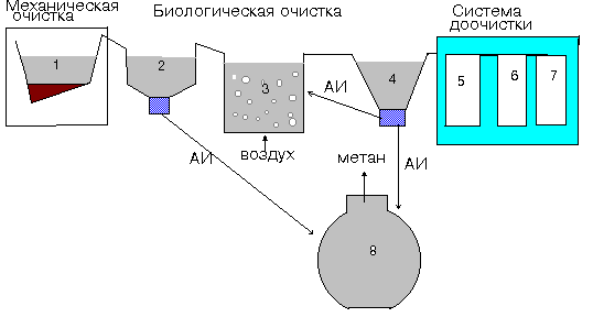
 4. Stations for deep biological treatment are already a more serious treatment plant, unlike a septic tank. This device requires electricity to operate. However, the quality of water purification is up to 98%. The design is quite compact and durable (up to 50 years of operation). To service the station at the top, above the ground, there is a special hatch.
Stormwater treatment plants

Despite the fact that rainwater is considered quite clean, however, it collects various harmful elements from asphalt, roofs and lawns. Garbage, sand and oil products. In order to prevent all this from falling into the nearest reservoirs, stormwater treatment facilities are being created.
In them, water undergoes mechanical purification in several stages:
- Sump. Here, under the influence of the gravity of the Earth, large particles settle to the bottom - pebbles, glass fragments, metal parts, etc.
- thin layer module. Here, oils and oil products are collected on the surface of the water, where they are collected on special hydrophobic plates.
- Sorption fibrous filter. It captures everything that the thin layer filter missed.
- coalescent module. It contributes to the separation of particles of oil products that float to the surface, the size of which is greater than 0.2 mm.
- Coal filter aftertreatment. It finally rids the water of all oil products that remain in it after passing through the previous stages of purification.
Design of treatment facilities
Design O.S. determine their cost, choose the right treatment technology, ensure the reliability of the structure, bring wastewater to quality standards. Experienced specialists will help you find effective plants and reagents, draw up a wastewater treatment scheme and put the plant into operation. Another important point is the preparation of a budget that will allow you to plan and control costs, as well as make adjustments if necessary.
For the project O.S. The following factors are strongly influenced:
- Waste water volumes. The design of facilities for a personal plot is one thing, but the design of facilities for wastewater treatment of a cottage village is another. Moreover, it must be taken into account that the possibilities of O.S. must be greater than the current amount of wastewater.
- Locality. Wastewater treatment facilities require the access of special vehicles. It is also necessary to provide for the power supply of the facility, the disposal of purified water, the location of the sewerage system. O.S. can occupy a large area, but they should not interfere with neighboring buildings, structures, road sections and other structures.
- Waste water pollution. Storm water treatment technology is very different from household water treatment.
- Required level of cleaning. If the customer wants to save on the quality of treated water, then it is necessary to use simple technologies. However, if it is necessary to discharge water into natural reservoirs, then the quality of treatment must be appropriate.
- Competence of the performer. If you order O.S. from inexperienced companies, then get ready for unpleasant surprises in the form of an increase in construction estimates or a septic tank that floated up in the spring. This happens because the project forgets to include enough critical points.
- Technological features. The technologies used, the presence or absence of treatment stages, the need to build systems serving the treatment plant - all this should be reflected in the project.
- Other. It is impossible to foresee everything in advance. As the treatment plant is being designed and installed, various changes may be made to the draft plan that could not have been foreseen at the initial stage.

Stages of designing a treatment plant:
- Preliminary work. They include studying the object, clarifying the wishes of the customer, analyzing wastewater, etc.
- Collection of permits. This item is usually relevant for the construction of large and complex structures. For their construction, it is necessary to obtain and agree on the relevant documentation from supervisory authorities: MOBVU, MOSRYBVOD, Rosprirodnadzor, SES, Hydromet, etc.
- Choice of technology. Based on paragraphs 1 and 2, the necessary technologies used for water purification are selected.
- Drawing up a budget. Construction costs O.S. must be transparent. The customer must know exactly how much the materials cost, what is the price of the installed equipment, what wage fund for workers, etc. You should also take into account the cost of subsequent maintenance of the system.
- cleaning efficiency. Despite all calculations, the cleaning results may be far from desired. Therefore, already at the planning stage, O.S. it is necessary to conduct experiments and laboratory studies that will help to avoid unpleasant surprises after construction is completed.
- Development and approval of project documentation. To start the construction of treatment facilities, it is necessary to develop and agree on the following documents: a draft sanitary protection zone, a draft standard for permissible discharges, a draft maximum permissible emissions.

Installation of treatment facilities
After the project O.S. has been prepared and all the necessary permits have been obtained, the installation stage begins. Although the installation of a country septic tank is very different from the construction of a treatment plant in a cottage village, they still go through several stages.
First, the terrain is being prepared. A pit is being dug for the installation of a treatment plant. The floor of the pit is filled with sand and tamped or concreted. If the treatment plant is designed for a large amount of wastewater, then, as a rule, it is built on the surface of the earth. In this case, the foundation is poured and a building or structure is already installed on it.
Secondly, the installation of equipment is carried out. It is installed, connected to the sewerage and drainage system, to the electrical network. This stage is very important because it requires the personnel to know the specifics of the operation of the configured equipment. It is improper installation that most often causes equipment failure.
Thirdly, checking and handing over the object. After installation, the finished treatment plant is tested for the quality of water treatment, as well as for the ability to work in conditions of increased load. After checking O.S. is handed over to the customer or his representative, and, if necessary, passes the procedure of state control.

Maintenance of treatment facilities
Like any equipment, a sewage treatment plant also needs maintenance. First of all from O.S. it is necessary to remove large debris, sand, as well as excess sludge that are formed during cleaning. On large O.S. the number and type of elements to be removed can be much larger. But in any case, they will have to be removed.
Secondly, the performance of the equipment is checked. Malfunctions in any element can be fraught not only with a decrease in the quality of water purification, but also with the failure of all equipment.
Thirdly, in case of detection of a breakdown, the equipment is subject to repair. And it's good if the equipment is under warranty. If the warranty period has expired, then the repair of O.S. will have to be done at your own expense.
production of treatment facilities